


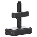


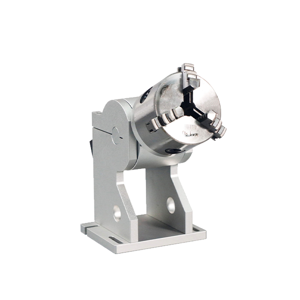
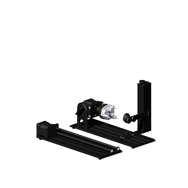


Physical Operation (Rotary A)
Table of Contents
1.Connect the Machine: Attach the fiber laser engraver to the rotary chuck A and place the rotary on the work table.

2.Clamp the Object: Use the anticlockwise mode to clamp a cylindrical object or the clockwise mode to support a ring.

3.Adjust Angle: If necessary, lift or lower the rotary chuck to change its angle for optimal marking.

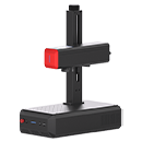
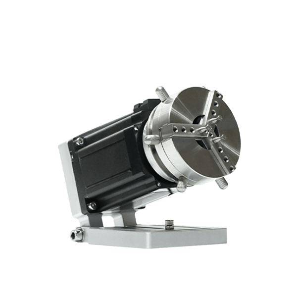
Physical Operation (Rotary B)
1.Connect the Machine: Attach the fiber laser engraver to the rotary chuck B and place the rotary at the correct angle as shown.

2.Clamp the Object: Use the positive mode or negative mode to clamp the cylindrical object as indicated.

3.Adjust Elevation: Elevate the rotary chuck with a support if needed to ensure the machine can mark at the right focus point.

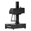
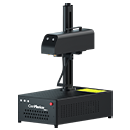
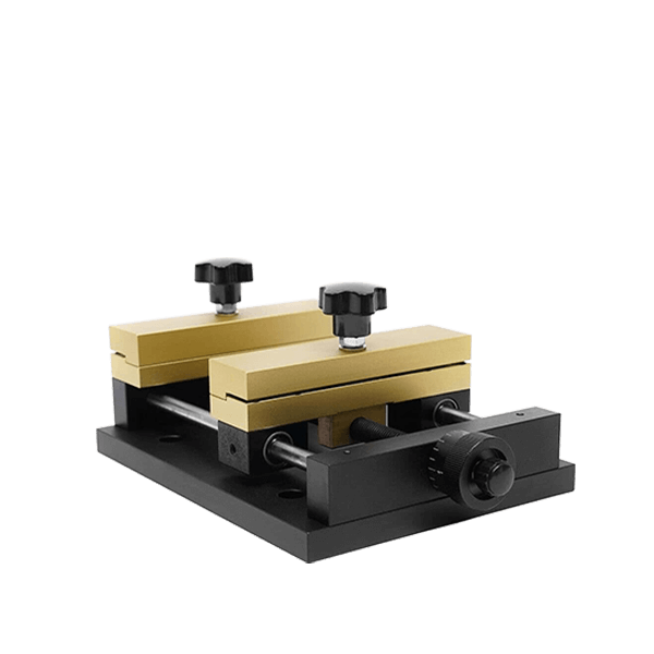
Physical Operation (Rotary C)
1.Connect the Machine: Attach the fiber laser engraver to the rotary chuck C.

2.Place the Object: Position the cylindrical object on the roller for marking.

Software operation
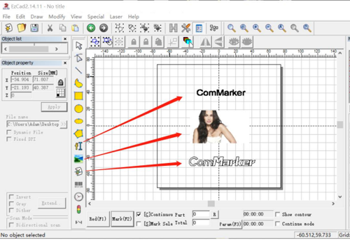
Text Marking
- Input Text:
- Enter the text you wish to engrave.
- Click “Apply” and then the “Center” button.

2.Enable Hatch Mode:
- Click the “H” button, tick “Enable”, and then click OK.
- Note: Do not tick “Mark Contour” or “All Cala”.

3.Select Laser Option:
- From the menu, select “Laser”.
- Choose “Rotate TextMark” for simple text marking.

4.Configure Parameters (Param F3):
- Click “Param (F3)” and set “configuration markcfg0”.
- Tick “Enable”.
- Input the pulses per round number as “12800”.
- Adjust scale compensation if necessary to affect text spacing.
- Tick “Reverse” if you want to change the marking order of the words.
- Select the appropriate axis (X or Y) based on the rotary’s placement direction.
- Click “OK (确认)”.

5.Preview and Mark:
- Click “Red (F1)” to preview; the red light area indicates the first letter of the first line.
- Press “ESC” to exit preview, adjust the rotary chuck location if needed.
- Ensure the red rectangle preview is on the top of the cylinder for level surface engraving.
- Click “Mark” to start engraving.

Graphics Marking
1.Import a Vector File:
- Click the “Draw vector file” button.
- Click “Put to Origin” button.
- Click the “H” button, tick “Enable”, and select “Z” hatch mode.
- Note: Do not tick “Mark Contour” or “All Cala”.
- Note: Bitmap files are not suitable for rotary cylinder marking.

2.Select Rotary Mark:
- In the menu, choose “Rotary Mark”.

3.Configure Split Line:
- Tick “Mark by split line”.
- Input the object diameter.
- Set the middle lines:
- Double-click to create a line.
- Right-click to delete a line.
- Drag with the mouse to move a line.
- Ensure the diameter number matches the object’s diameter.

4.Force All Split (Alternative):
- Tick “Force all split”.
- Input the object diameter and adjust the “Split Size”.

5.Configure Parameters (Param F3):
- Click “Param (F3)” and set the parameters.
- Tick “Enable”.
- Input the pulses per round number as “12800”.
- Tick “Reverse” if you want to change the marking order of the words.
- Select the appropriate axis (X or Y) based on the roller’s placement direction.
- Click “Rotate Axis”.
- Adjust the Gear Ratio number to avoid overlaps or gaps in the marking graph:
- A higher number reduces overlap.
- A lower number reduces gaps.
- Test different numbers for accuracy (to two decimal places) until satisfied.
- Click “OK (确认)”.

6.Preview and Mark:
- Click “Red (F1)” to preview; the red light area shows the first part divided by the split line.
- Press “ESC” to exit preview, adjust the rotary location if needed.
- Click “Mark” to start engraving.

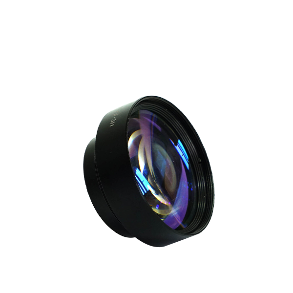
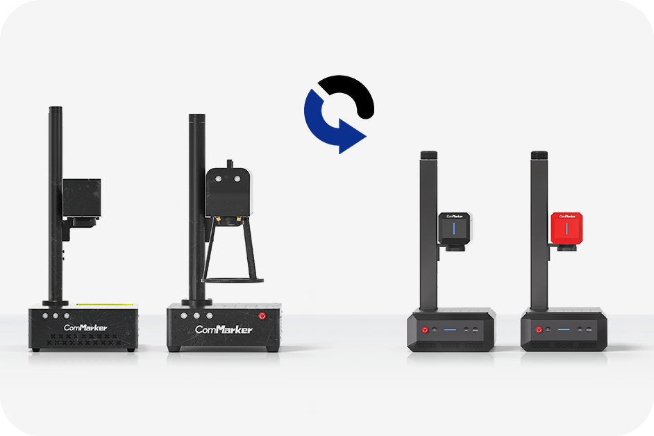
How to Replace the 110mm Field Lens with a 200mm Field Lens on a Fiber Laser Engraver?
Installation Steps
Step 1: Install the 200mm Field Lens
- Remove the 110mm lens by unscrewing it by hand.
- Install the 200mm field lens by screwing it in place.

Step 2: Re-adjust the Focus
- Adjust the focus since the focal length changes with the new lens.
- Refer to the operation manual, specifically the section on adjusting focus.
Step 3: Field Lens 9-Point Calibration
1.Open Calibration Software
- Open the USB folder.
- Open the “EZCAD for ComMarker” folder.
- Select the 200mm folder.
- Open the software “CorFile2” (ensure EZCAD is closed first).

2.Set Laser Source Parameters
- Click “F1”, set laser source parameters, select “IPG” and click “OK”.

3.Prepare Calibration Surface
- Stick two pieces of paperboard together on the back cover with tape.
- Place it on the work table ensuring the paperboard is flat.

4.Mark Calibration Points
- Click “F3” to mark a 9-point rectangle. The graph will display the marked points.

5.Adjust Pattern to Match Marking
- Click the button on the top-right corner to change the pattern until it matches the marking on the paperboard.

6.Measure and Input Coordinates
- Measure the coordinate position of each point on the paperboard.
- Use point 5 as the center coordinate (0,0).
- Input the measured coordinates into the corresponding columns in the dialog box.
- Click “OK” to save and return to the upper interface.
Note: Ensure the ruler is absolutely horizontal or vertical and measurement lines go through the 9 points.

7.Generate Calibration File
- Click “F6” to generate a calibration file.
- Specify a file name (e.g., “200 B4 ComMarker”).
- Save the file and remember the directory location.

8.Verify Calibration
- Click “F7” to verify calibration.
- Open the saved calibration file.
- Click “F8” to mark the calibrated rectangle.
Note: If the marked rectangle is regular, the calibration is successful. If deformed, recalibration is necessary.


9.Import Calibration File in EZCAD2
- Import the calibration file for the 200mm lens in EZCAD2.
- Refer to the operation manual for importing correction files.
Parameters for Marking a Photo
Note: The following parameters are suggestions for a 20W machine engraving stainless steel. Results may vary based on file size, materials, and focal length. Adjust parameters as needed for different machines or materials.
Parameters for B4 20W with 110x110mm Area on Stainless Steel
Input the parameters in the engraving software.
Fine-tune contrast and brightness of the picture for clearer engraving.

Parameters for B4 20W with 110x110mm Area on Painted Metal
Adjust the parameters according to the specific material.

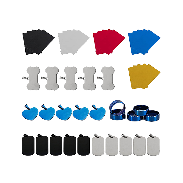
Parameters for Marking Different Colors
Note: The following parameters are suggestions for a 20W machine engraving stainless steel. Adjust parameters as needed for different machines or materials.

Lightburn Operation Tutorial for MacOS
1.Download and Install Lightburn Software
Download from Lightburn Software.
Ensure the Lightburn version is V1.3.01 or higher.

2.Install Lightburn Software
Drag the Lightburn icon to the Applications folder.

3.Copy EZCAD Folder
Copy the folder “EZCAD for ComMarker B4” from the USB to the desktop.

4.Set Up Device
Open Lightburn, click “Create Manually”, and select “JCZ Fiber”.
Ensure the machine is on and connected via USB.

5.Import EZCAD Config and select the appropriate folder.

6.Select folder “110mm” (or 200mmaccordingtoyourlens)—->“ Plug”, and choose “markcfg7” andclick“next”

7.You can see the following window if everything goes right, and click “next”

8.Change the name if necessary, and input therightXandY Axis Length according to the lens. Click “next”

9.Click “finish” and it will in the device list

10.The status will change into “Ready” whenthemachineison and connected via USB

11. Go to “Basic Settings” from “Device setting” button, click “Load COR file”, Select “EZCAD for ComMarker B4”—>“110mm”, Choose file “JCZ11.cor”, Click “OK”

12.Change the setting of Freq “Min 20”, “Max 200”. Switchon “Galvo 2”. And it is ready to control themachinewithLightburn.*(Please refer to step 11 for MOPAmachine)

Special Setting for JPT MOPA fiber
13.Change the setting of Freq “Min 1”, “Max 4000”. Switch on “Galvo 2”. Switch on the button “Enable Q-PulseWidthSetting” (Make sure the Fiber Type is “IPG _YLP” or “JPT”)

Lightburn Operation Tutorial for Windows
- Follow the same steps as for MacOS.
- Install the necessary driver when installing Lightburn software.