


Introduction:
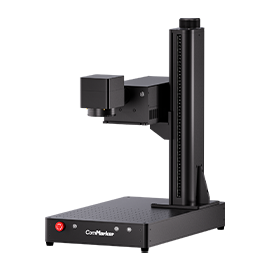
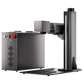
The ComMarker B4 Fiber Laser Engraver introduces a groundbreaking approach to laser engraving on PCB boards, renowned for their hardness and wear resistance. This introduction explores the vital realm of parameter optimization, specifically delving into power, speed, and frequency adjustments crucial for achieving precision in engraving while preserving the integrity of PCB material. As a beacon of versatility and precision, the ComMarker B4 emerges as a key player in industrial engraving. This concise overview sets the stage for a detailed exploration of parameter fine-tuning, offering insights and recommendations. By uncovering optimal settings, this advancement ensures the seamless integration of technology, enabling intricate designs, clear markings, and durable engravings on PCB boards, propelling the capabilities of laser engraving to new heights.
Basic information:
|
Software |
EZCAD |
|
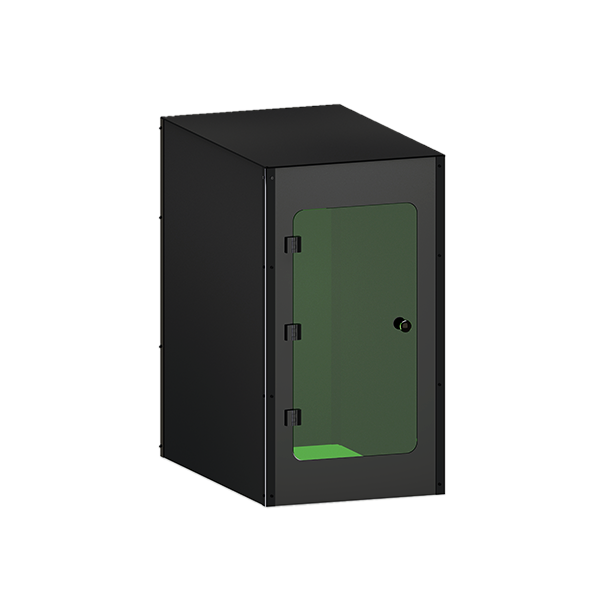
Machine |
|
|
Laser Module Output Power |
60W |
|
Material Used |
PCB |
|
Material Info |
PCB board |
|
Making Time(mins) |
30s |
Setting:
For filling only:
|
Process Method |
Filling |
|
Process Material |
PCB board |
|
Speed(mm/s) |
2000 |
|
Max Power(%) |
60 |
|
Pass |
6 |
|
Line space |
0.03 |
Instruction:
Step 1: Design the Circuit Diagram
Initiate the laser engraving process by meticulously crafting the circuit diagram that corresponds to the desired specifications for the PCB board. Ensure accuracy and precision in the design to reflect the intended functionality of the circuit.
Step 2: Input the Circuit Diagram into EZCAD
Utilize the user-friendly interface of EZCAD to seamlessly transfer the meticulously designed circuit diagram. This software facilitates a smooth transition from the digital design phase to the practical implementation on the ComMarker B4 Fiber Laser Engraver.
Step 3: Set the Parameters
Fine-tune the engraving parameters on the ComMarker B4, considering factors such as power, speed, and frequency. Calibration at this stage ensures optimal engraving performance and material preservation.
Step 4: Preview and Adjust Position and Size
Preview the circuit diagram on the PCB board using the ComMarker B4’s preview functionality. Make necessary adjustments to the position and size, aligning the digital design with the physical dimensions of the PCB board for precise engraving.
Step 5: Laser Engraver It
Initiate the laser engraving process, allowing the ComMarker B4 to translate the digital circuit diagram onto the PCB board. Monitor the engraving procedure closely to ensure adherence to the set parameters.
Step 6: Check the Result
Upon completion, carefully examine the engraved PCB board. Verify that the markings align with the intended circuit design and assess the overall quality of the engraving. This step ensures the accuracy and functionality of the engraved circuit on the PCB board, confirming a successful laser engraving process.
Conclusion
In conclusion, the process of laser engraving a PCB board with the ComMarker B4 Fiber Laser Engraver involves a systematic series of steps that seamlessly bridge the digital design phase to the tangible realization of a circuit. Commencing with the intricately crafted circuit diagram and its translation into EZCAD, the user navigates through parameter setting, a critical step for achieving optimal engraving results. The preview stage, coupled with adjustments to position and size, refines the alignment of the digital design on the PCB board, ensuring precision.
Executing the laser engraving process marks a pivotal moment, where the ComMarker B4 brings the circuit diagram to life on the robust PCB material. Finally, the thorough examination in the concluding step ensures the accuracy and functionality of the engraved circuit, affirming the success of the entire process. This systematic approach, blending technology, precision, and user oversight, underscores the efficiency and reliability of the ComMarker B4 Fiber Laser Engraver in achieving high-quality results in PCB board engraving applications.